About our receive antennas
With a keen interest in low-band DXing, particularly on 160 meters, we have done a lot of experimenting with receive antennas and made use of the work done by others. Over the years the mainstay receive antenna at AA1K locations was the Beverage, typically a long, low single wire fed at one end through a matching transformer and terminated at the other end with a non-inductive resistor to a ground rod. I first learned of this antenna in the 1970s when listening to K1PBW, Ernie, in western Massachusetts, easily working DX stations that I couldn’t even hear from my QTH just south in Connecticut. Ernie had resurrected an antenna invented by Harold Beverage in the 1920s but that had not been in common use by hams.
Around this time in the 1970s, I also often held late-night QSOs on 160 meters with W8JI, Tom, who was doing many experiments with phased loops and other arrays of antennas in Ohio. Tom, later after he moved to Georgia, also made popular arrays of phased Beverages, another invention from the 1920s that had seen little if any use by hams. Tom also devised arrays of short vertical antennas with a unique top-hat design that has become popular among the hard-core DXers on 160 meters.
WW2Y, Peter, and K2WI, Rob, also did extensive work with stagger-phased Beverages in New Jersey in the 1990s, and Peter presented this work at the Dayton Hamvention antenna forum.
“Low Band Antennas,” the comprehensive book by ON4UN, John, now in its fifth edition, also has provided a wealth of ideas.
Here is the rundown of receive antennas we have erected at AA1K in Delaware. The two transmit arrays on 160 also can be quite useful for receiving. Details on those are found on another page.
Beverage antennas
Beverages all about 10 feet high unless noted otherwise. Named for the inventor, not the drink.
14 degrees heading: Single-wire 600-foot Beverage for northern Europe and central Asia.
37 degrees: Single 950-foot long Beverage, for Europe. This had been one half of a broadside phased pair spaced 200 feet, but the other element was 50-80 feet from several new houses built next door and was picking up too much RFI from them so was removed. Even as a single wire, this continues to generally be my best antenna for receiving Europe.
45 degrees: Stagger-phased pair of 800-foot Beverages, spaced 25 feet apart and staggered 132 feet, for Europe. Fixed phasing. Variable phasing with NCC-1. This pair was rarely better than the single 950-foot Beverage and in 2021 the feedlines were repurposed for a new West stagger-phased pair.
45 degrees: A stagger-phased pair of 525-foot Beverages, spaced 30 feet apart and staggered 132 feet for Europe. Fixed phasing. These were my first stagger-phased pair and worked quite well when installed around 2000, but they rarely were used after installation of better and longer phased Beverages. In 2021, these two wires were replaced with a new stagger-phased pair of about 1500 feet long. They use the original fixed phasing using a 1/4 wave delay line. Completed just before the CQ 160 meter CW contest, this proved to be the best antenna for Europe the first night and was generally the best antenna in the 2022 CQ 160 meter CW contest.
45-degrees: This is a broadside-endfire array using four Beverage elements, each 560 feet long. It started out as a simple broadside pair spaced about 350 feet. This was about equal to the single-wire 950-foot Beverage most of the time, sometimes better. Then I added two more elements, inside the other two and about 25 feet — so they are spaced about 300 feet broadside and forward staggered about 100 feet. Typical spacing in such and array is to feed the two outer wires together and then combine those. For simplicity I simply fed the two inner wires together to a T, and RG6 from that T and the T connecting the two outer wires run to the shack and are connected to the A and B inputs of a DX Engineering NCC-1 phasing box. This allows for optimizing the null off the back of the array. This array is also most distant from my transmit antennas (600 feet at feedpoints) and can be used for listening in-band while transmitting on 160.
The above Beverages of different lengths toward Europe often produce distinct layers of signals arriving at different wave angles. During contest pileups, switching between them often produces different signals that can be copied — a different one on each antenna. I also have used the NCC-1 phasing box to combine the 950-footer and the 800-foot pair as a 3-element stagger-phased array.
75 degrees: Broadside-phased pair of 500-foot Beverages, spaced 400 feet. Fixed phasing. This was a great antenna for the Mideast and northern Africa, but construction of homes next door brought noise sources that made this antenna less effective and it is currently in standby mode.
105 degrees: Broadside-phased pair of 600-foot Beverages, spaced 400 feet. Fixed phasing. Excellent for southern Africa when there is activity.
135 degrees: A single-wire, 1300-foot long Beverage. When the VK0EK expedition to Heard Island was upcoming in 2016, I realized I had no Beverage antenna favoring that direction. I had about 2000 feet of No. 18 copper wire that I had unwound from a massive old high-voltage transformer. I mapped out a location and stretched it through the trees. This helped put a new country in the log on 160.
162 degrees: Single 540-foot Beverage, 3 feet high. Zig-zags along what surveyors called a “meandering ditch” along property line. It originally was 880 feet and more effective at that length, but was shortened to minimize RFI pickup when new homes were built nearby. Excellent for Caribbean and South America.
180 degrees: Single-wire 500-foot Beverage, 10 feet high. Another of similar length is only 3 feet high and generally quieter.
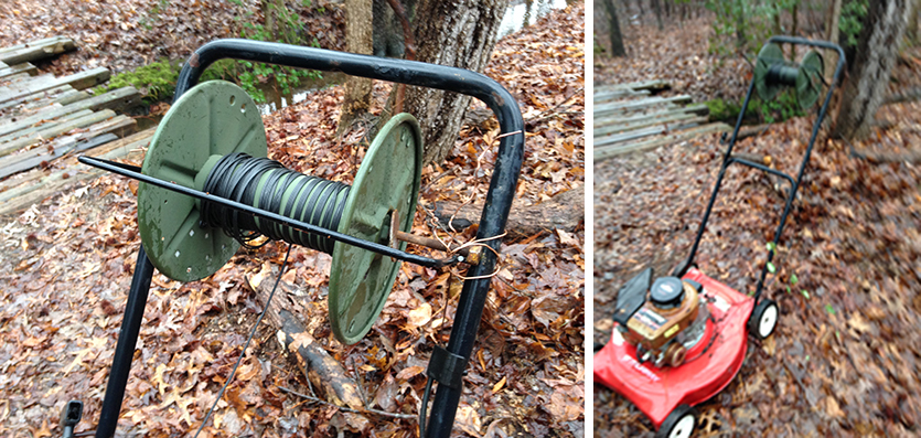
180 degrees: Stagger-phased pair of 810-foot Beverages, spaced 20 feet broadside and staggered 100 feet. Length determined by space available and it was convenient to cut in half a 500-meter (1640-feet) spool of WD1A military surplus wire. The two wires of the WD1A are shorted at each end. Feedline from each matching transformer runs to an NCC-1 phasing box in the radio room. I installed this antenna on the fly one day in January 2017 when XW4ZW was about to be QRV on 160. I chose 7 feet for the height since this was convenient to achieve without having to haul my stepladder along. For testing in daylight, I tuned in a local broadcast station 60 miles away that was S9 on the K3 meter, and when I tweaked the NCC-1 for best null the BC signal dropped into the noise.
210 degrees: Single-wire 600-foot Beverage, responsible for most skewed-path contacts into Southeast Asia (XU, HS, XZ as well as DU).
245 degrees: Single-wire 550-foot Beverage for ZL and south Pacific.
270 degrees: Stagger-phased pair of 810-foot Beverages using WD1A wire installed in 2021. Broadside spacing of about 25 feet and stagger of 132 feet. Separate feedlines run to NCC-1 phasing unit in the shack.
290 degrees: Single-wire 750-foot Beverage for VK and Pacific.
320 degrees: Broadside phased pair of 935-foot Beverages, spaced 175 feet, for JA/KL7/Northern Pacific. Fixed phasing. These run close to several of the towers and thus pick up noise from them but they still tend to be the best antenna for hearing JA.
320 degrees: Single-wire 500-foot Beverage for JA/KL7/Northern Pacific, and is usually much quieter than the longer phased pair and sometimes hears better.
342 degrees: Stagger-phased pair of 880-foot Beverages spaced 3 feet, staggered 132 feet, for DU/BA/BV/JT. Variable phasing with NCC-1. It was put up quite a few years ago when I was chasing DU9/N0NM for a new one and I heard him almost daily with this as a single wire and later phased pair. But we never worked (I later worked another DU station coming in skewed path from the SSW).
342 degrees: Stagger-phased pair of 450-foot Beverages spaced 3 feet, staggered 132 feet, for DU/BA/BV/JT. Fixed phasing. These started out as a 750-foot pair but they ran beneath the power line feeding our house and picked up too much noise. So we shortened. Typically they hear about the same as the longer stagger-phased pair in same direction.
160 meter short receive verticals (W8JI-style)
Each element about 22-feet high with four 22-foot sloping top-hat wires.
2-element (later 4-element): Endfire spaced 70 feet, producing NE/SW cardiod pattern and other directions by use of separate feedlines to DX Engineering NCC-1 phasing box. Performance similar to single-wire 500-foot Beverage. This was my original antenna when I purchased the NCC-1, and it was later expanded to a 4-element broadside/endfire array with 297-foot by 70-foot spacing, favoring NE/SW, with variable phasing (performance similar or better than long phased Beverages). Elements are 2-inch diameter aluminum about 22 feet tall with four 22-foot top-hat wires, small loading inductor at base (about 30 uh) and series swamping resistor have loading inductor (about 50-60 ohms). 20 radials each about 25 feet long under each element, with a single copper ground rod at base of each element. This antenna has since been replaced with one of same dimensions but using 36-foot wire elements (no top hat) hung from trees and located farther from the TX antennas after we purchased some additional property. At feedpoint we match with 150-ohm swamping resistor and 2:1 matching transformer on BN202 core.
4-element broadside/endfire array: Broadside spaced 317 feet and endfire 70 feet, separate from the 4-element version mentioned above. Spacing Elements are aluminum tubing from old beam parts, about 22-feet tall with four 22-foot top-hat wires. 16 radials each about 25 feet long under each element and a single copper ground rod at base of each element. Broadside orientation favors NE/SW, variable with use of separate feedlines from forward pair and rearward pair going to NCC-1 phasing box. Installed with coax simply connected directly to the elements, no matching or swamping resistors. Performance equals or exceeds results with phased Beverages. Also some useful directivity on 80 meters despite broad spacing on that band. This antenna has since been replaced with one of same dimensions but using 36-foot wire elements (no top hat) hung from trees and located farther from the TX antennas after we purchased some additional property.
160 meter broadside/endfire short receive verticals (ON4UN-style elements)
Each element 11 meters high, no top hat wires.
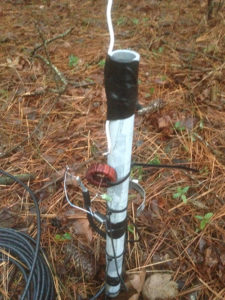
After experimenting with the above short verticals for several years, I decided in late 2016 to try some new versions positioned farther from my transmit antennas, the main power line and other noise sources. While I initially considered a full 8-circle array for this position, I decided to make separate arrays for different directions to allow for optimizing the pattern for rejection of noise from certain areas where there were homes and power lines, typical RFI sources. One goal was to use base-loaded elements to eliminate the top-loading wires of the W8JI-style antennas. Falling tree limbs in our forest make these top-hat wires a constant maintenance issue.
ON4UN in his Low Band DXing book had described his use of base-loaded elements when he placed a mini 4-square receiving array in his front yard, where top-loading wires could not be used. John had constructed his elements with a combination of steel and aluminum, and they were 11 meters tall. Since I had more wire and trees on hand than steel and aluminum, I chose to use tree-supported wires for my elements. The wires were each cut to 11 meters tall and supported with Dacron rope placed over tree limbs with an air gun. They have proven to work quite well. Even in their preliminary hook-up, when I simply connected the wires directly to the feedlines, without any matching or swamping resistors, they often equal or exceed long Beverages in performance. Gain improves, however, with the elements matched to the feedlines.
The first set constructed was oriented favoring Europe (broadside favoring NE/SW).
……………………………..NE…………………………
1—————————-T————————-2
3—————————T————————-4
……………………………..SW…………………………
Broadside spacing (between elements 1, 2 and 3, 4) is about 305 feet. Endfire spacing (between 1,3 and 2,4) is about 146 feet. I say “about” since positioning in dense woods is difficult. But they are close to these numbers. Equal length feedlines were cut from a 1,000-foot spool of RG6 CATV coax, making them 250-feet long each. Extra length was coiled near the elements to perhaps offer some choking to minimize any common mode pickup.
I initially used these with the coax center conductor just connected directly to the wire elements (no. 12 stranded, insulated THHN), and the shield to a single ground rod about 4-5 feet long at each element. The coax from 1-2 is paired at a T with no matching yet, and 3-4 also are paired. These go to a switch box where a relay selects either this set or the NW/SE array (for JA), then two long feedlines (each is a combination of RG6 and CATV 75-ohm, 3/4 inch hardline, not identical lengths) that run to the radio room where they are connected to the “A” and “B” inputs of the NCC-1.
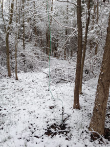
The performance even in this “primitive” stage, without matching, is amazing. S-9 signals will drop into the noise when the phase is reversed on the NCC-1. Often the BS/EF is better than the long phased Beverages — time will tell if one or the other becomes the dominant receive antenna here. With the un-matched BS/EF, signal levels are lower than on the Beverages so I find it necessary to adjust the RF gain on the K3 to compensate as I’m listening.
A few days before the CQ WW 160-Meter CW Contest (Jan. 2017), I decided to try improving this BS/EF set by adding the matching at each element. Following ON4UN’s lead, I wound each base-loading coil on a T-130-2 toroid core. But I found my elements needed more inductance, perhaps because the wire elements are thinner than what John used. I ended up with about 94 uh on each, then made final adjustments by squeezing or separating the turns. This was tedious as I had used small wire I had on hand — no. 26 enamel — and next time I will try no. 24 or 22 if it will fit on the core, so it will be less “springy” during adjustments. Once I had it in place I used a plastic wire tie to keep the windings from moving at each end. The elements without matching were resonant around 6.8 mHz, and with the toroid each was adjusted around 1.83 mHz, plus/minus about 5 kHz. I also added two quarter-wave radials under each element, opposite each other, and this lowered the resonant frequency some (final adjustment to 1.83 mHz was done after all the radials were down. They were simply laid on the ground).
NO3M, Eric, had suggested to me on the Low Band Chat that instead of simply using a swamping resistor to match each element to 75 ohms, I swamp with a higher value to make it 300 ohms and then use a 4:1 transformer to match to the feedline, this making the element more broad-banded. ON4UN had used that method on 80 meters but not on 160. Since I often operate in contests high in the band (1880-1900 kHz on CW, even higher on phone), I decided to go this route. For now, I’ve ended up with a 150-ohm swamping resistor at each element. The impedance at each element (as measured with my Rig Expert AA-230 Zoom analyzer) varies, ranging from 264-290 ohms or so. I was running out of time to try and tweak this any further before the contest, and the antenna worked quite well with the “rough” matching and 4:1 matching coil wound on a BN-202 binocular core. The coax shield is NOT connected to the element ground rod, only to the wires of the matching coil.
There is still the mismatch at the T connectors where the feedlines from the two elements (1-2) and (3-4) are joined, but the antenna still plays quite well and the gain has improved over the un-matched version.
I continue to use the NW/SE array without any matching or radials. There is a single ground rod on each element, about 3-4 feet long.
……………………………..NW…………………………
1—————————-T————————-2
3—————————-T————————-4
………………………………SE………………………….
As in the other BS/EF set, elements 1 and 2 are paired, and 3 and 4 are paired at each “T” junction without matching. A relay box selects these for the long runs of feedline to the shack where they are connected to the “A” and “B” inputs on the NCC-1. To optimize the nulls for my local noise sources, as well as to accommodate the space available and make use of available trees for supports, the element footprint on this set is 327 feet by 70 feet. These elements are made of No. 10 stranded THHN insulated wire. RG6 feedlines are each 194 feet long (I didn’t have a full spool available) and they go to their T junctions about 60 feet from the relay box, so there are coax runs from the T’s to the relay box before being switched to the long runs to the shack.
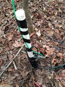
The front-to-back on this set is quite impressive as it was on the NE/SW set without any matching. To paraphrase one of ON4UN’s statements in an early edition about Beverages, these antennas just “want to play.”
While I could have used fixed phasing delay lines on these arrays, as W8JI, Tom, did quite successfully on the ones he devised and used in the 8-circle configuration, the advantage of using the NCC-1 (which Tom designed for DX Engineering) is it allows for tweaking the array for the best null in any circumstances. ON4UN had suggested this could be done by using relay-selected delay lines of different lengths, but the NCC-1 provided the ultimate capability by giving a full range of choices. The needed null may change with time, either as soil conditions change with the seasons, or as different noise sources arise, so having the variable phasing allows for constant optimization of this rejection.
I have done some A/B testing with the original BS/EF short vertical array that uses W8JI-style top-loaded elements, and thus far I have not been able to see any difference in the performance (although the new one is quieter due to distance from some power line noise).
The Monday morning after the CQ 160 meter contest, I was hearing numerous JA stations about equally well on the several Beverages in that direction and on the unmatched BS/EF short vertical array.
Some of these short vertical elements are placed as close as 10-20 feet from a Beverage wire. I have not found any indication that they are suffering from coupling — there was no variation in the element matching on the ones close to these wires.
Since I was planning to leave the matching exposed while I went through development of these antennas, I was curious if there was any impact from rain or snow. I hooked up a test setup of my matching coil and swamping resistor, connected to the AA-230 analyzer, and dipped them in a bowl of our fresh well-water. There was a drop in the resonant frequency, perhaps 100 kHz, and I’ve found that the antennas seem to work find even when these components at the base are soaked by rain or snow.
Other resources on short verticals: W5ZN, Joel, has written up his experience in installing the W8JI-style array and this is an excellent step-by-step account of the procedure. And W3LPL, Frank, has presented an excellent talk at Dayton and elsewhere on low-band receiving antennas. Here’s the PowerPoint from it.
Small receiving loop
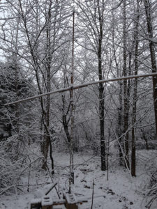
I hadn’t played with a small receiving loop for more than 15 years, but when K3ZM, Peter, mentioned he was using one so he could receive while transmitting during the 160 meter contests, I decided to take another look. Peter, in case you haven’t noticed, is consistently the no. 1 single-op contender from the USA in the 160-meter contests, from his seaside location in Virginia. While my original use of these small loops dated back to the 1960s and a W1FB design in ARRL publications, more recent development has been described by W8JI and N6RK. While the remnants of the last one I built (about 5 feet in diameter around the year 2000 for a radio club talk) are still on the “old projects” pile, I decided to start with a new, larger one to maximize gain.
The new one used some scrap wood for supports, some small coax for the loop element (total length about 40 feet), and an old multi-section broadcast variable capacitor for tuning. In my typical open-air breadboard fashion for quick projects, there was no box around the capacitor, and the connections were just soldered and left unprotected. I built this a few days before the 2016 CQ 160-meter CW contest, but ran out of time to put it into use. It sat off to the side but I decided to see how it might do a few days before the 2017 contest. I had stretched some new hardline out previously so only had to run about 300 feet of RG6 to position the antenna where it would be about 1300 feet from my transmit array.
I attempted to do my initial testing with a little Alinco DX11T all-band handheld receiver, but found that at 1.8 mHz this receiver was not sensitive enough to properly make the adjustments. But it did show me the antenna was in fact working, more or less as the original was designed. Having gotten some other last-minute antenna repairs out of the way, I decided to take one more stab at the loop.
This time, I took one of my K3 transceivers and put a 12-volt deep-cycle battery on a hand truck and hauled this out to the loop antenna. I didn’t disconnect the feedline, since it was soldered directly, but just used some alligator clips to hook up a short piece of coax from the K3. When everything was ready, I turned on my other K3 with a tenth of a watt and set it as a beacon through the transmit antenna with my call ID’ing as I went back to the loop. With the K3 connected, I had no problem hearing my transmitted signal and was able to quickly find the null, which is broadside to the plane of the loop. This is a very sharp null and very deep.
I lashed down the loop in this position and removed the K3 and battery. Returning to the shack, I hooked the K3 back up in the No. 2 radio position and hooked up the long feedline from the loop. With the two radios in SO2R mode, I could now listen across the band while transmitting full power into the array. Even when the TX array was aimed in the same direction as the loop, I could hear weak signals within a few kHz of my transmit frequency while I was transmitting. I was amazed at how I was able to hear many weak DX signals on this receiving loop, and it was responsible for finding many of my multipliers during the contest. I could also switch in one of my Beverages to the second radio for comparison, about 800 feet from the transmit array, but it was swamped too much by the transmitted signal to allow listening for anything but the strongest signals on the second K3 while I was transmitting.
While my transmitted signal across the band was knocked down sufficiently to make this a very useful asset during the contest, I suspect refining the construction as suggested by W8JI and N6RK would make it even more effective in minimizing the transmitted signal on the second receiver.
Short verticals for in-band receiving
In January 2022 I decided to try another approach for in-band receiving while transmitting on 160. My “temporary” large receiving loop had fallen into disrepair so I decided to try a set of endfire phased short verticals. I repurposed two elements from one of my original bs/ef arrays. These were 2-inch OD surplus military antenna tubing, bolted together at the joints to make a 22-foot element. I added another 11 feet of smaller aluminum tubing to get a total element length of 33 feet. These verticals are self-supporting and survived a heavy snowstorm the first week they were up. They are mounted on 4x4x6′ treated wood posts set with 3 feet in the ground. PVC tubing insulates the element from the post and the mounting bolts. I placed some 2″ copper strap in the hole before inserting the post and this serves as my ground rod for each. Each element is fed with RG6; the center conductor is simply connected directly to the base of the element without matching. The shield goes to the ground strap. The RG6 goes to an NCC-1 phasing unit in the shack, about 1300 feet away. I was out of time to add any matching when I built these just before the 2022 CQ 160 meter CW contest and they worked quite well for tuning the band while transmitting. I picked up many new stations and some multipliers. The spacing is 132 feet, chosen as diagrams of phasing patterns in the antenna book show this gives the deepest null off the rear of the array.
